Basic DSP Lab
Description
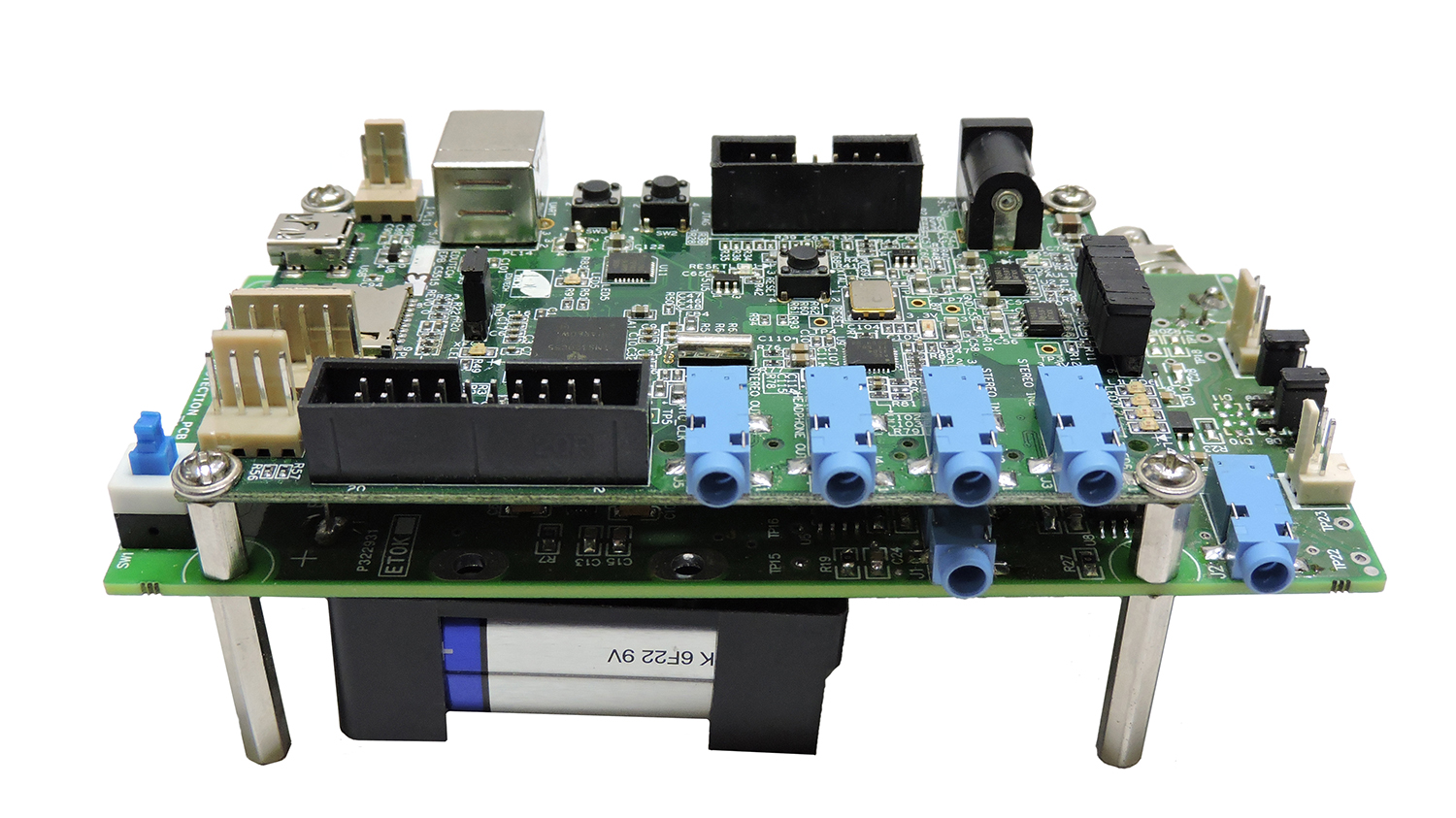
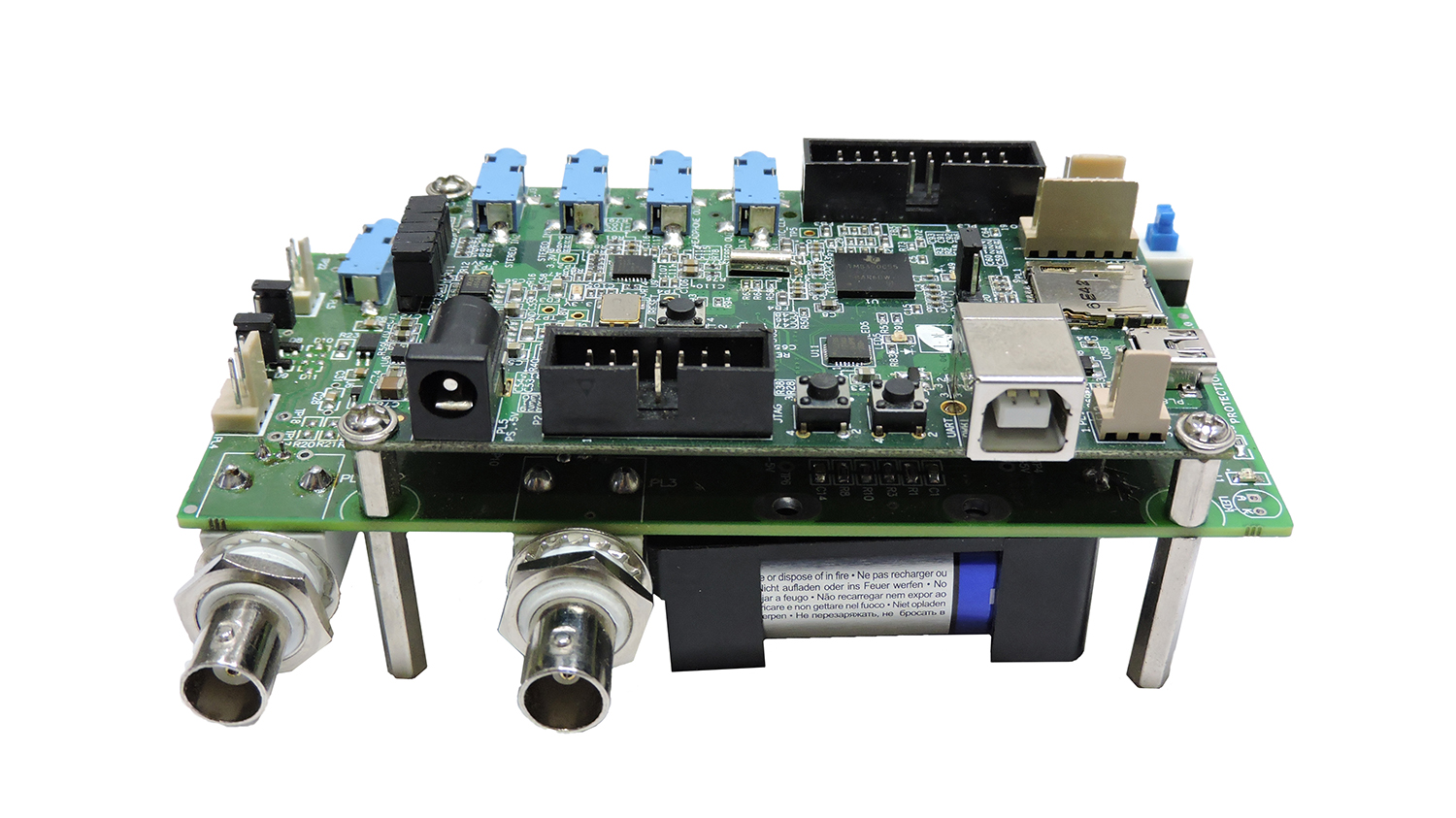
The basic DSP lab offers a complete solution to learn the basic concepts of Signal Processing. The lab offers set of DSP CPU board along with the emulator and accessories which can be used to perform hands-on experiments to justify the concepts involved in the signal processing. The easy integration with the Code Composer Studio tool and the debug features enable the user to easily implement and test the code. The lab consists of experiments covering Basic DSP operation and audio processing.
Features
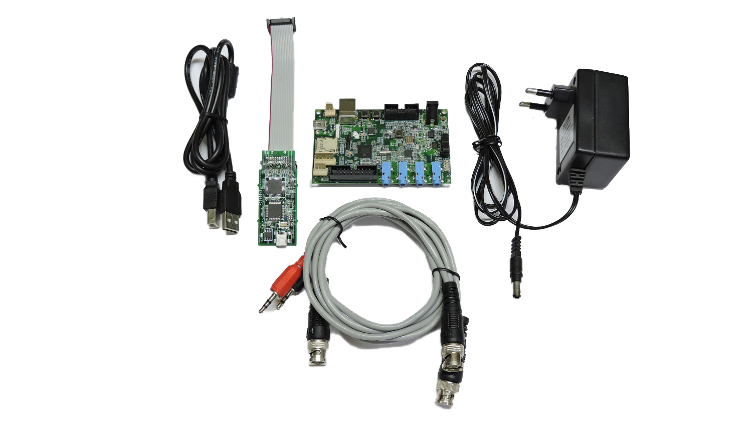
The basic DSP lab consists of the following resources:
1. Basic DSP kit with Code Composer Studio CD/DVD
2. USB JTAG Emulator - XDS100_v2
3. Cable Accessories
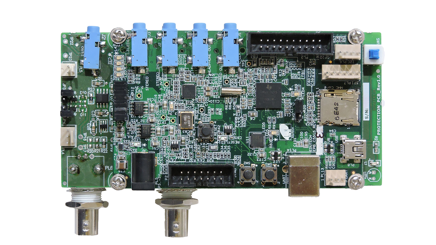
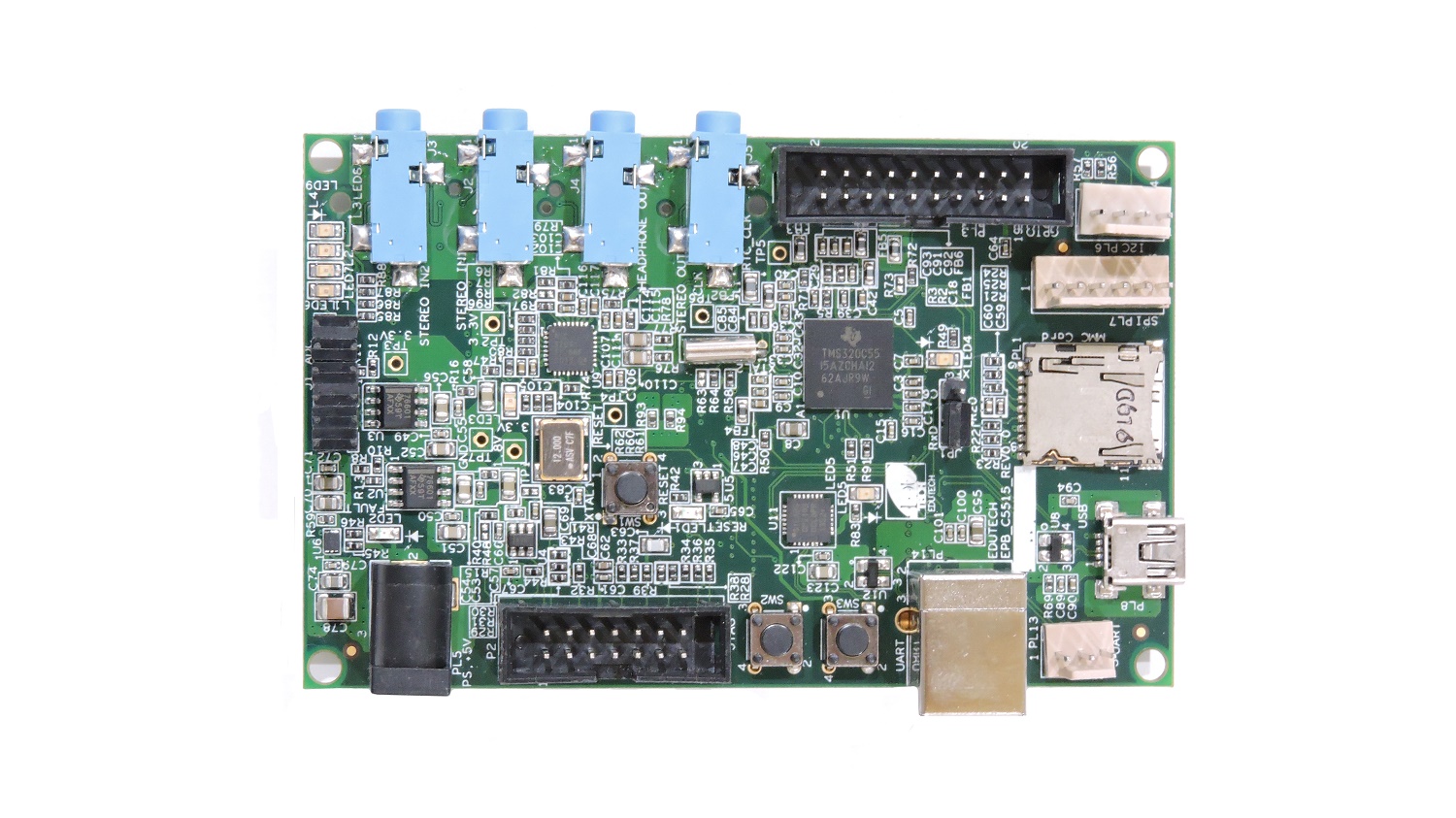
DSP Board Features
Mechanical Parameters
- Size: 99mm x 62.5 mm
- Power Supply - 5V DC
Processor
- TMS320C5515 – Fixed Point Digital Signal Processor
- DSP with up to 60, 75, 100, 120 MHz Clock Rate
- On board JTAG emulation connector
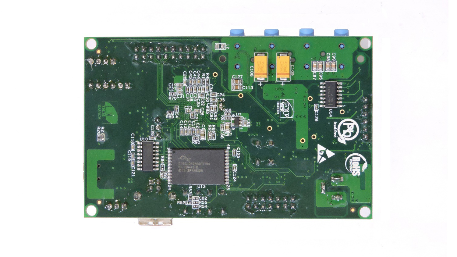
Memory
- On board 32MB Flash Memory (3V 70ns Parallel NOR Flash Memory)
- 320K Bytes Zero-Wait State On-Chip RAM, Composing of:
- 64K Bytes of Dual-Access RAM (DARAM), 8 Blocks of 4K x 16-Bit
- 256K Bytes of Single-Access RAM (SARAM), 32 Blocks of 4K x 16-Bit
- 128K Bytes of Zero Wait-State On-Chip ROM (4 Blocks of 16K x 16-Bit)
On board Data Transfer Interfaces
- 3 pin header for UART interface
- USB TYPE B Connector for UART interface for Debug Console
- Mini USB Type AB Connector for USB device interface
- SPI based micro SD card interface
- 6 pin relimate connector for SPI communication
- 4 pin relimate connector for I2C communication
On board Input/output Interfaces and other Facilities
- 20 Pin GPIO connector
- 3.3V Power-On LED indication
- Reset Switch with LED indication
- 4 User LED at GPIO Pin as GPIO Test point
- ADC based 2 user push buttons for various applications
- 10 bit 4 channels Successive Approximation ADC input facility
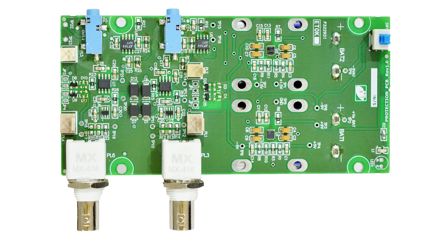
On Board Special functionality
- Audio jack for Headphone out
- Audio jack for Stereo out
- Audio jack for Stereo In1
- Audio jack for Stereo In2
- LED to indicate power surge
- LED to indicate high voltage input
- LED indication for USB connection for Debug Console
- Various test points for various signals
- Jumper selection to switch UART between USB connector and 3 pin connector for RXD line
USB JTAG Emulator - XDS100_v2 Features
- Supports Texas Instruments Processors and Microcontrollers with JTAG interface viz. F28xx, C674x, C64x+, ARM9, C54xx, C55xx, Cortex™ etc
- Supports Embedded Trace Buffer (ETB) on selected TI devices
- USB Bus Powered
- Supports USB 2.0 (480mbps)
- Debug features (Emulation Connect/Disconnect, Read/Write memory, Read registers, Load program, Run, Halt, Step, Software and Hardware Breakpoint support, Real-Time Mode)
- Compatible with +1.8V or +3.3V JTAG Interfaces.
- Supports targets with 14-pin JTAG Header
- Dimensions: 2.22”L x 1.”W Low Profile
- 14-pin JTAG Header
- Compatible with Code Composer Studio IDE™ from Texas Instruments version v4 and later
- Supports UniFlash™ programming utility from Texas Instruments
- Compatible with Windows XP, Vista, Win7, Wn10 and Linux Operating Systems
- Adaptive clocking
- LED light to indicate active USB connection
- Enclosure for safer use
Experiments
- Write a "Hello World" program and execute on EPB_C5515 target board using CCSv5 or later.
- Write a program to blink single XF LED on EPB_C5515 target board.
- Import a program to blink 4 user LED's on EPB_C5515 target board.
- write a program for Basic file I/O for CCS5.3 usinng EPB_C5515 target board (i.e reading/writing data from/to a file stored in your system into code composer studio)
- Generate sine wave signals to the CCS Graph window using data file from the PC.
- Generate square wave signals to the CCS Graph window using data file from the PC.
- Write a program for basic signal generation for CCS5.3 using EPB_C5515 target board.
- Write a program for re-generation of sine wave for CCS5.3 using EPB_C5515 target board.
- Write a program to control gain of AIC3204 coded for EPB_C5515 target board.
- FIR Filter implementation using Linear Buffering (C Coding).
- FIR FIlter implementation using Linear Buffering (Assembly Coding)
- Write a program to implement linear buffering using EPB_C5515 target board using assembly language function for "linearbuff()"
- Fixed-Point Implementation
- FFT and Spectrum Analysis
- Overlap Save method for Filtering using FFT,.
Contents :
| Resources | Quantity |
|---|---|
| Educational Practice Board for TMS320C5515 | 10 |
| USB JTAG Emulator | 10 |
| 5V Power Supply | 10 |
| Cable Set for DSP (C5000) Kit | 10 |