All-In-One DSP Educational Practice Board
Description
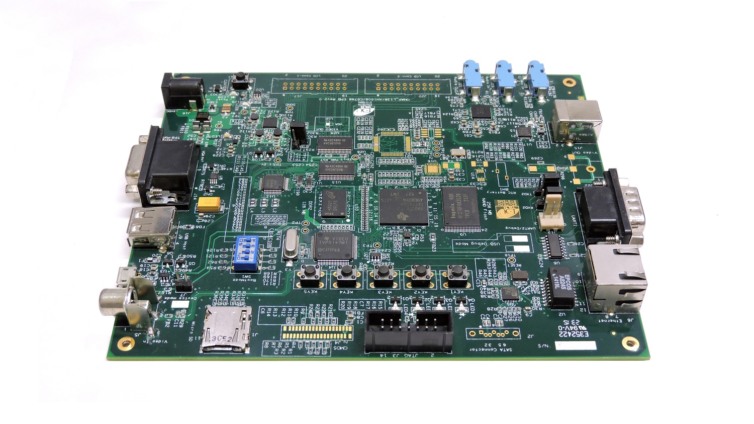
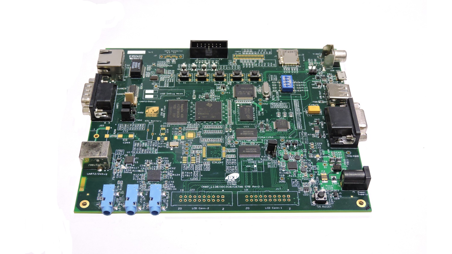
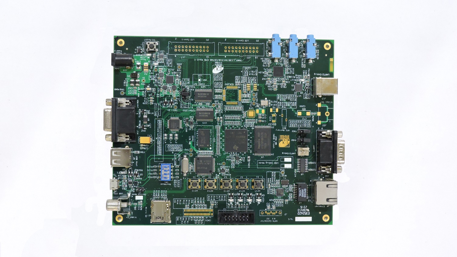
The All-in-one DSP 6000 Educational practice Board is a specially designed board around TI6000 Platform. This board is an alternative to the DSK6713 board which has limited features. This board offers features like image, audio and video processing on a single board thus offering many on-board features like camera input interface and VGA features for easy output interface. You can use the PC monitor as an output device for display of Image and Video. You do not need and other out put devices like TV. This board can be used for performing more lab experiments which involves topics like image, and video processing. This board can be effectively used for performing hands-on activities and experimentation of DSP hardware. Lot of experimentation with solution is made available in the form of DSP lab workbook and can be used by UG and PG students. This board enables the the confidence amongst the student to perform the experiments on the DSP hardware with the help of well documented lab workbook. A special training session for the DSP lab is also made available upon request of the user.
Features
Processor
- TMS320C6748 – Fixed/ Floating Point Digital Signal Processor
- DSP with up to 456 MHz performance.
- On board 14 Pin (2x7 Pin) JTAG emulation connector
- Boot mode selection switch
Memory
- On board 256 MB Flash memory
- On board 128 MB DDR2 RAM memory
Data Transfer Interfaces
- On board DB9 connector for UART-1 interface
- On board 3 pin header for UART-2 interface
- On board USB TYPE B Connector for UART-2 interface for Debug Console
- LED indication for USB connection for Debug Console
- On board Reset Switch with LED indication
- On board USB Type A Connector for USB host interface
- On board micro USB Type A Connector for USB OTG interface
- On board RJ45 connector for 10/100 Ethernet interface
- On board I2C based Temperature sensor
- On board I2C based RTC interface with battery backup
- On board SPI based micro SD card interface
- On board provision for SATA connector
Input/Output Interfaces and other Facilities
- On board Power-On LED indication
- On board 4 User LED at GPIO Pin as GPIO Test point
- On board 5 user push buttons for various applications
Special functionality
- Boot mode selection switch
- On board Video in port available
- On board VGA out connector
- On board Provision for composite video out
- Provision for Graphics LCD interface
- On board audio jack and speaker (Mic in) interface
- On board audio codec for speaker out
- Provision for CMOS sensor connector to interface CMOS camera
- On board Temperature sensor with interrupt out facility
- On board jumper selection to switch various video out options
- On board LED to indicate power surge
- On board LED to indicate high voltage input
- On board excessive voltage protection circuit with LED indication
- Various test points for various signals
- On board jumper selection to switch UART2 between USB connector and 3 pin connector