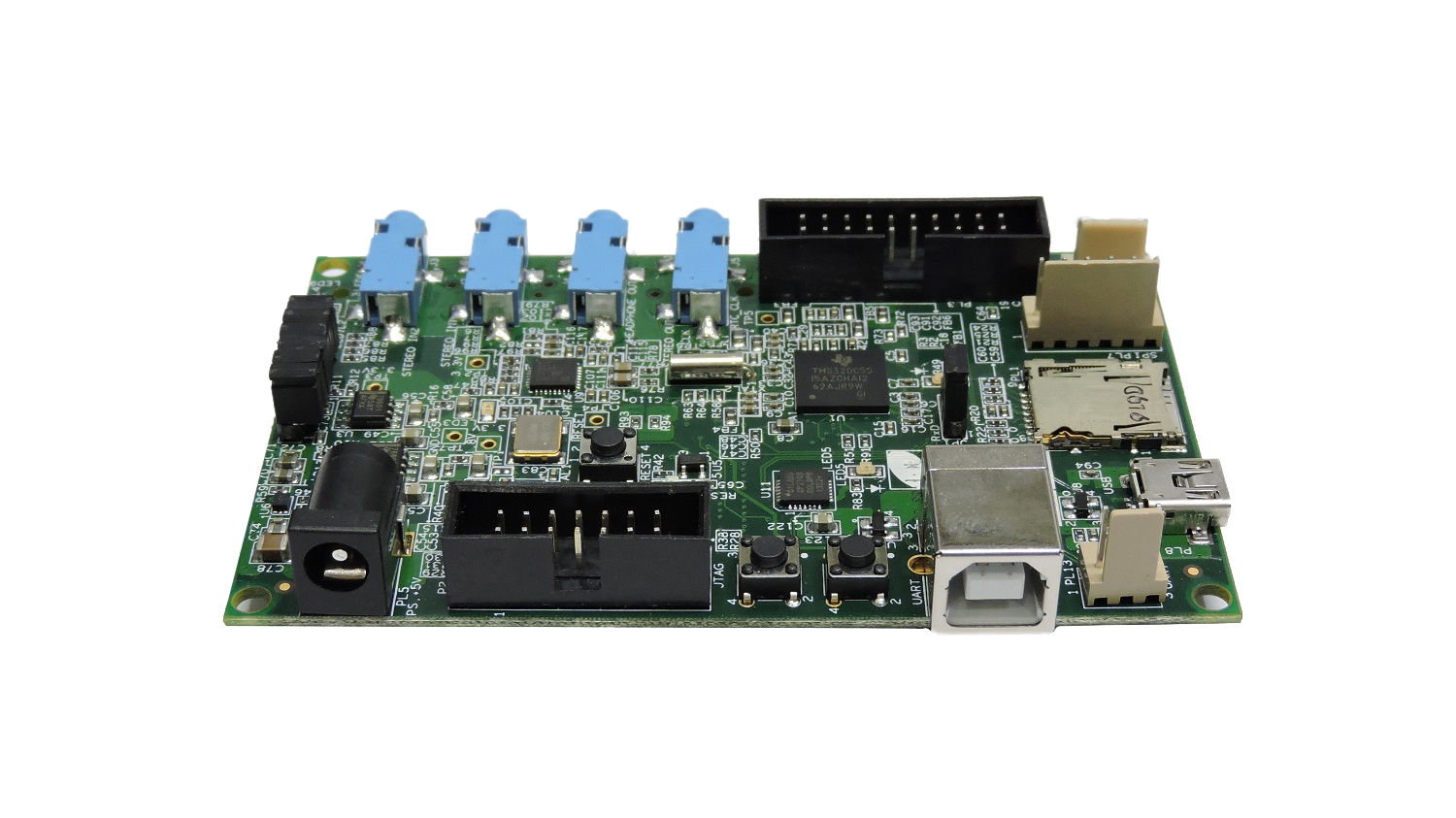
Educational Practice Board for TMS320C5515
Description
The EPB_C5515 is a stand-alone module permitting engineers and software developers to evaluate certain characteristics of the TMS320C5515 DSP and determine processor applicability to design requirements.
To simplify code development and shorten debugging time, a C5000 Code Composer Studio driver is provided. In addition, an onboard JTAG connector provides interface to emulators, for assembly language and ‘C’ language debug.
Features
Mechanical Parameters
Size: 99mm x 57.42mm
Input Voltage - 5V DC
Processor
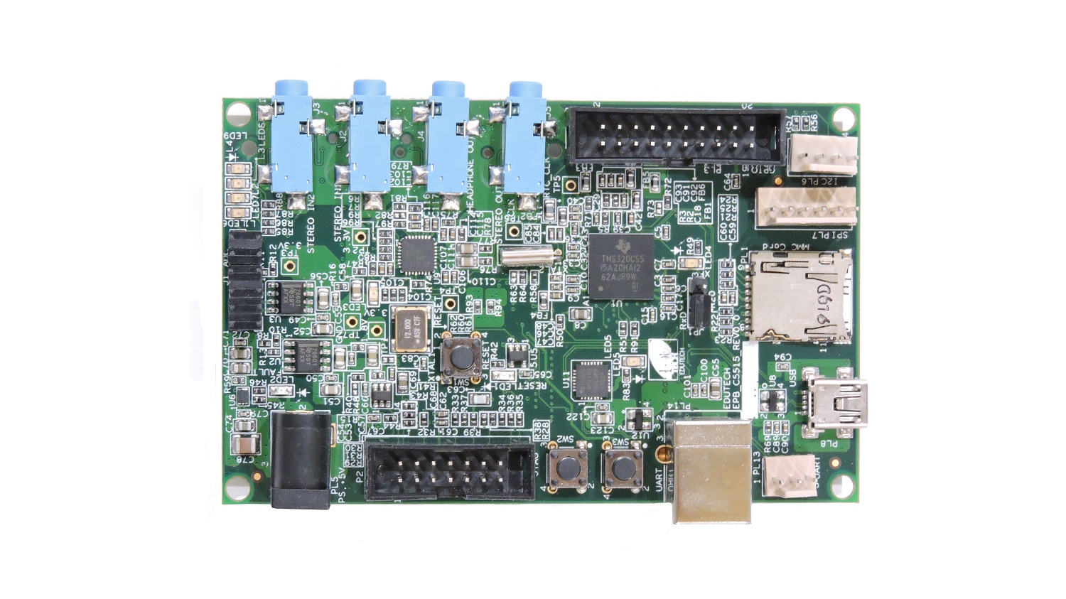
TMS320C5515 – Fixed Point Digital Signal Processor
DSP with up to 60, 75, 100, 120 MHz Clock Rate
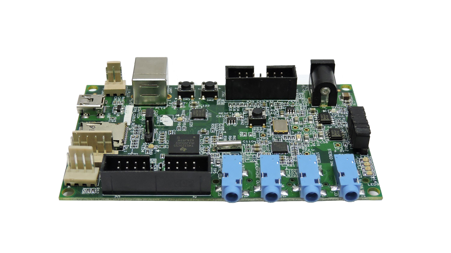
14 Pin (2x7 Pin) on-board JTAG emulation connector
Memory
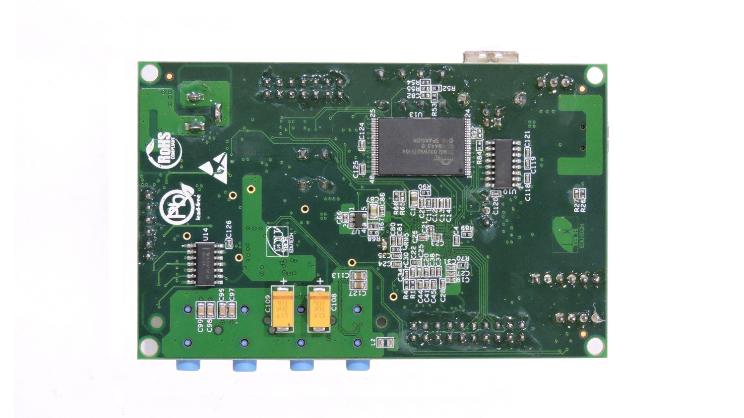
Onboard 32MB Flash Memory (3V 70ns Parallel NOR Flash Memory)
320K Bytes Zero-Wait State On-Chip RAM, Composed of:
• 64K Bytes of Dual-Access RAM (DARAM), 8 Blocks of 4K x 16-Bit
• 256K Bytes of Single-Access RAM (SARAM), 32 Blocks of 4K x 16-Bit
128K Bytes of Zero Wait-State On-Chip ROM (4 Blocks of 16K x 16-Bit)
Data Transfer Interfaces
On board 3 pin header for UART interface
On board USB TYPE B Connector for UART interface for Debug Console
On board Reset Switch with LED indication
On board Mini USB Type AB Connector for USB device interface
On board SPI based micro SD card interface
On board 6 pin relimate connector for SPI communication
On board 4 pin relimate connector for I2C communication
Input/Output Interfaces and other Facilities
On board 20 Pin GPIO connector
On board 3.3V Power-On LED indication
On board XF LED indication
On board 4 User LED at GPIO Pin as GPIO Test point
On board ADC based 2 user push buttons for various applications
On board 10 bit 4 channels Successive Approximation ADC input facility
Special functionality
On board audio jack for Headphone out
On board audio jack for Stereo out
On board audio jack for Stereo In1
On board audio jack for Stereo In2
On board LED to indicate power surge
On board LED to indicate high voltage input
On board excessive voltage protection circuit with LED indication
LED indication for USB connection for Debug Console
Various test points for various signals
On board jumper selection to switch UART between USB connector and 3 pin connector for RXD line